
1-805-484-2992
Quotes - Engineering - SalesThe loop behind the jacket
How a jacket loop holds a tenth of a degree
The culture never sees a heat exchanger. It sees the vessel wall, and the wall sees jacket water that a temperature control unit circulates at 20 to 200 gpm through a dimple jacket or half-pipe coil. The TCU is a pump, a small steam-to-water heater, a small water-to-chilled-water cooler and a controller. A 2,000 liter mammalian reactor at 37 C might need 3 kW of cooling at peak cell density and 1 kW of heating in the lag phase, with the culture never moving 0.1 C.
This page is about the two exchangers inside the TCU: the sizing case, the loop volume the controller needs, the interlocks, and the 4 to 45 C range.
Sizing case, loop volume, interlocks and the temperature range
The sizing case is the cool-down, not the run
Metabolic heat at peak is 2 to 4 kW on a 2,000 liter mammalian culture and 200 to 400 kW on a 20,000 liter microbial fermenter. Those are the numbers people size on, and they are not the largest duty. The largest is bringing 20,000 liters of freshly sterilized medium from 121 C to 37 C in the two to four hours the schedule allows, 1 to 2 MW on a large fermenter, three to five times the run cooling. The cooler is sized on that cool-down at summer chilled water, and the run then happens at 10 to 20 percent of capacity, which is the turndown the controls must handle. The heater is small by comparison, 20 to 100 kW.
Loop volume is a control component
A cooler that can remove 1 MW on a loop holding 50 gallons will cycle: the valve cracks, the loop drops 5 C in seconds, the valve slams shut, the culture RTD has not moved, and the controller hunts. The loop is given volume on purpose, a 100 to 500 gallon buffer tank on a large fermenter, so the exchangers change its temperature slowly enough for the cascade to follow. The culture controller sets a jacket supply setpoint limited to 2 to 5 C from the culture, and the exchangers hit that. The cooler valve is characterized for the low end of its range; an oversized linear valve is the usual reason a jacket loop hunts.
Keeping steam and 7 C water away from the culture
Live steam into a jacket loop is a vessel full of dead cells. The heater is a steam-to-water exchanger, never direct injection, and the supply carries a high limit at 50 to 55 C that closes the steam valve independently of the controller. On the cold side, 7 C chilled water straight into the jacket of a 37 C culture stresses cells at the wall, so the cooler is indirect too and the supply low limit sits 10 C below setpoint. Both exchangers live on the TCU skid, the one piece of equipment in the suite that runs on plant utilities with no sanitary finish: the loop water never touches the culture, and a plain U-tube in 304 is the right and economical answer.
4 C holds, 45 C thermophiles and the common mistake
The same TCU that holds a culture at 37 C holds harvested broth at 4 C overnight, which means 30 percent glycol in the loop and a cooler working against 2 C glycol at a 2 to 3 C approach. Thermophilic and some yeast fermentations sit at 42 to 45 C and need heater capacity against room loss. The exchangers are rated for the whole envelope from the first order so the suite is not rebuilding the TCU when the product changes.
The common mistake is sizing the cooler on run load and finding the cool-down takes eight hours, or sizing it on the cool-down with a valve that cannot control at run load. Send HeatX the vessel volume, organism, cool-down time, setpoint range and utilities, and the heater, cooler, valves and loop volume come as a set. Call and talk it through with an engineer: 1-805-484-2992


Bioreactor jacket loop process conditions
The jacket loop is a utility circuit, and the rows below describe how it is sized and controlled. Compare them with your vessel volume and culture setpoint, and send your plant utilities with the quote request.
| Condition | Detail |
| Product | Jacket water or 30 percent glycol, closed loop, no product contact |
| Flow range | 20 gpm on a 200 L vessel to 200 gpm on a 20,000 L fermenter |
| Temperatures in / out | Setpoint 4 to 45 C; jacket supply within 2 to 5 C of the culture |
| Hold | None; the loop runs continuously for the 7 to 21 day batch |
| Utility | Plant steam 15 to 30 psig or 90 C water; chilled water 7 C or glycol -5 C |
| Approach | Cooler 3 to 5 C; heater 20 to 40 C, throttled hard |
| Construction | U-tube or straight-tube shell-and-tube in 304 or 316; brazed plate on small units |
| Finish / class | Utility grade, not sanitary |
| Control | Supply temperature cascaded from the culture RTD; high limit 55 C on the supply |
| Cleaning | Closed treated loop; no CIP or SIP |
Common FAQs
The wall would sit at 7 C against a 37 C culture, killing cells at the wall and making the controller fight itself. A tempered indirect loop keeps the wall within a few degrees of the culture.
No. The jacket loop is closed and never touches product. Utility-grade shell-and-tube or brazed plate in 304 or 316 is standard.
Cascade control: the culture RTD sets a jacket supply setpoint in a narrow band, and characterized valves on a volume-buffered loop hold it.
Yes, as central hot and cold headers with a mixing station at each vessel, sized on the coincident peak.
Related
Applications
CBD Extraction
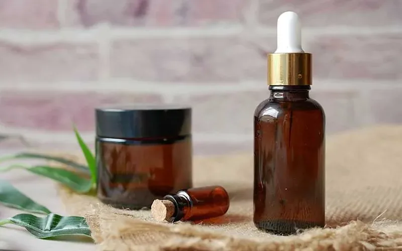
Cold ethanol in, crude out, solvent back to the tank: the four exchangers on a hemp line and how each is sized
+ Learn More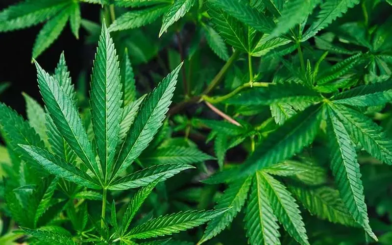
Applications
Cannabis
Hydrocarbon, ethanol or CO2: the solvent decides the exchangers, the area classification decides the skid.
+ Learn More
Applications
Ethanol & Solvent Chilling
Below -20 F the fluid on the cold side is the design, and the exchanger is sized on it, not on the solvent.
+ Learn More