
1-805-484-2992
Quotes - Engineering - SalesCondensing on a surface the product is allowed to touch
A sanitary vapor condenser receives vapor from an evaporator, a still, a cooker or a vessel vent and condenses it against cooling water, chilled water or glycol. When the vapor is product, as it is in aroma recovery, spirit and extract distillation and vapor recompression, or when the condensate is returned to product, the condensing surface is product contact and is polished, seal welded and drainable like any sanitary exchanger. When the vapor is water driven off an evaporator and the condensate goes to drain, the design is still sanitary on the side that could ever contaminate the process.
Two arrangements are common. A horizontal shell and tube with vapor on the shell side and water in the tubes gives the most condensing surface in the least length and is the usual choice for evaporator vapor. A vertical unit with vapor inside the tubes and water on the shell drains condensate straight down the tube walls, keeps the product surface a set of polished bores, and is preferred when the condensate is product or when a subcooled outlet is wanted.
Either way, the parts of the design that a liquid exchanger does not have are the vapor inlet, the vent and the condensate outlet, and each is placed on purpose.
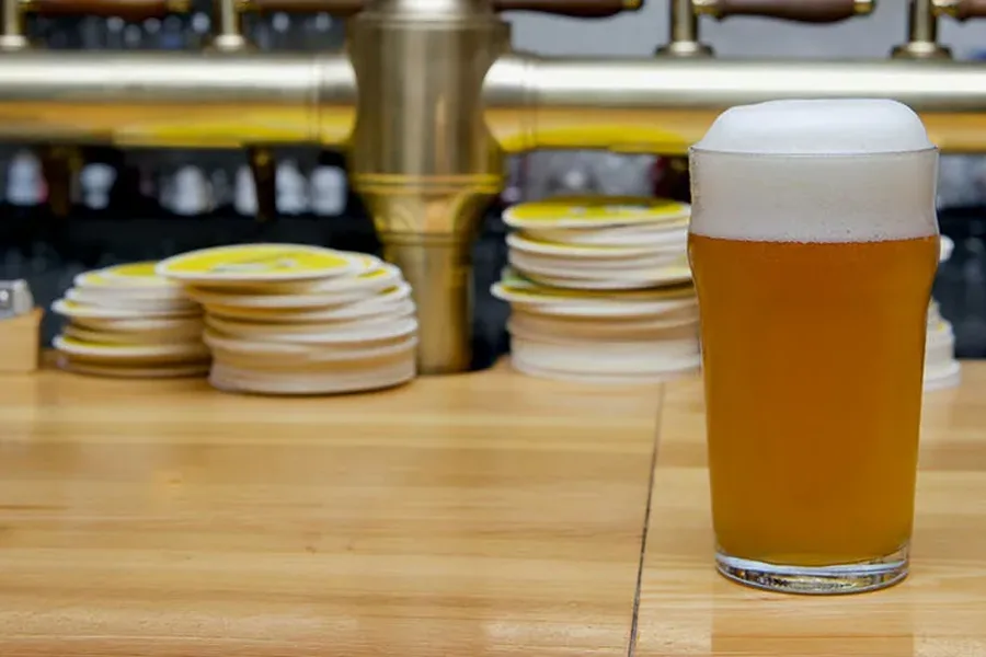
A condenser that cannot vent its air runs at half its rating and nobody can tell why. The vent is the design.
Vapor inlet, vent and condensate outlet placed for the duty, on polished sanitary surfaces.
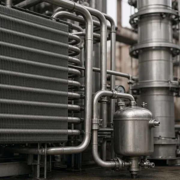
Venting designed in
- Non-condensables swept out before they blanket tubes
- Vent sized for the expected gas load
- Vent condenser recovers product vapor from the gas line
- Oversized inlet nozzle with impingement plate
- Low inlet velocity protects the first tube rows
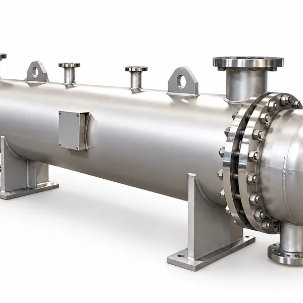
Clean surface, clean condensate
- Polished seal welded surface where vapor is product
- Vertical downflow drains condensate without pooling
- Outlet at true low point with loop seal
- Subcooling section holds volatiles in the liquid
- Spray ball reaches every wetted surface for CIP
Built To
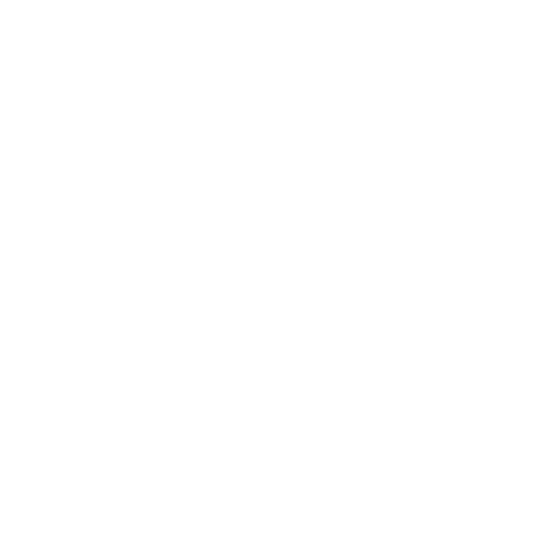

Sanitary vapor condenser, typical build
This is the build normally quoted when a condenser must handle vapor, vent and condensate cleanly. Your vapor rate, vacuum level and cooling water go with the request, and anything that changes the build changes the quote.
| Feature | Detail |
| Arrangement | Horizontal shell-side condensing, or vertical tube-side condensing with downflow |
| Tubes | 3/4" or 1" OD, 304L or 316L, 32 Ra or better where product contact, seal welded |
| Vapor inlet | Oversized nozzle with impingement plate; velocity kept low to protect the first rows |
| Vent | Non-condensable vent at the far end of the vapor path, sized for the expected gas load |
| Condensate outlet | At the true low point; loop seal or trap as the system requires |
| Subcooling | Optional flooded section or separate aftercooler |
| Cooling medium | Tower water, chilled water or glycol, 3 to 6 ft/s in the tubes |
| Vacuum service | Shell calculated for full vacuum on evaporator and distillation duty |
| Design pressure | 150 psig typical with full vacuum; higher on request |
| Codes | ASME VIII Div 1 U-stamp, 3-A or ASME BPE as specified, PED, CRN |
Designing sanitary condensers that make their rating
Evaporator vapor and vacuum
The last effect of a food evaporator produces low-pressure water vapor at 105 to 130 F, and the condenser is what holds the vacuum. It must condense the full vapor load against the available cooling water and pass the remaining non-condensables to the vacuum pump at a pressure the pump can handle. Vapor velocity into the shell is kept low because at 27 in Hg vacuum the specific volume is very large; the inlet nozzle is often the full diameter of the vapor line and the shell is sized on velocity before it is sized on area. Tubes are 304L on the water side and the shell is polished only if the condensate is returned to product.
Product vapor: aroma, spirits, extracts
When the vapor is the product, the condensing surface is product contact. Aroma recovery on juice evaporators, spirit condensers on stills, extract concentration and solvent evaporation for botanical products all condense vapor whose liquid is collected and sold. The tubes and shell on the vapor side are polished to 32 Ra or better, the condensate drains completely to a sanitary outlet, and CIP reaches every surface the vapor wetted. Vertical tube-side condensing is preferred here because the polished bores are easy to clean and the condensate runs straight down to the outlet without pooling. Sanitary condenser options by service are covered in more depth on our sanitary vapor condenser pages.
- Polished condensing surface, seal-welded tubes
- Vertical downflow for full drainage
- Subcooling section to hold volatiles in the liquid
- Spray ball on the vapor side where the geometry needs it
Venting and subcooling
Air leaks into vacuum systems and dissolved gases come out of solution as product boils; both end up in the condenser and both collect at the coldest, farthest point. The vent is placed there so the non-condensables are swept out rather than allowed to blanket the surface. A vent condenser, a small second unit on the vent line, recovers any product vapor that would otherwise leave with the gas. Where the condensate must be held below its bubble point to keep volatiles, a subcooling section at the bottom of the shell or a separate aftercooler brings it down a further 10 to 30 F.
Condensate removal and drainage
Condensate must leave as fast as it forms. The outlet sits at the true low point of the shell or tube side in the installed orientation, the unit is pitched toward it, and a loop seal, barometric leg or trap is provided so vapor does not blow through. A condenser that floods with its own condensate loses surface to subcooling and its capacity falls with it. On sanitary duty the same outlet is the CIP drain, and the design confirms that no baffle window or nozzle stub holds liquid when the unit is emptied.
A condenser designed around its vapor inlet, vent and drain will make its rating on day one and on day one thousand. Call and talk it through with an engineer: 1-805-484-2992
Common FAQs
Shell side, horizontal, for water vapor from an evaporator where surface per length matters and the condensate goes to drain. Tube side, vertical, when the condensate is product, when full drainage of a polished surface matters or when a subcooled outlet is wanted.
The usual cause is non-condensables blanketing the cold end because the vent is missing, undersized or in the wrong place, followed by flooding from a condensate outlet that is not at the low point. Both are design placements, not capacity problems.
Yes. Evaporator and distillation condensers are calculated for full vacuum on the shell and the vapor-side nozzles are sized for the large specific volume at those pressures.
When the condensate carries volatiles that would flash at the outlet, or when the downstream vessel needs it below saturation. A flooded section in the condenser or a small separate aftercooler adds 10 to 30 F of subcooling.
Tower water is usual for evaporator vapor because the condensing temperature is above it. Chilled water or glycol is used for aroma, spirit and low-temperature extract condensers where the condensing temperature is close to ambient. The medium sets the tube-side design and the approach.
Food and beverage condensers follow 3-A practice with polished product surfaces and drainable design. Pharma and extract condensers follow ASME BPE in 316L with electropolish and documentation where the specification calls for it.
Related
Sanitary Exchangers
Evaporators
Concentration under vacuum on polished tubes: falling film, rising film and forced circulation.
+ Learn More
Sanitary Exchangers
Clean Steam Generators
Plant steam in the tubes, treated water in the shell, and steam clean enough to touch product out the top.
+ Learn More
Sanitary Exchangers
Evaporators & Condensers
Phase change with a sanitary surface: concentrating product, condensing vapor and raising clean steam.
+ Learn More